Skippers need to have a basic knowledge of boat electrics, to avoid potential problems and to be able to solve them when they happen. The basic principles are easy enough to grasp, but as I have discovered, the challenges involved in rewiring a boat are more demanding…

When I bought my present boat, the state of the wiring was truly shocking (excuse the pun). Although the 35 year old Contessa had two nearly new batteries the wiring itself was in a dismal state, with many exposed and corroded connections. It was also in a disorganised tangle made worse by the fact that a succession of instruments and electronics had been added, replaced or removed over the years.
We made some temporary repairs in 2014 to get the nav lights working, but this year decided to bite the bullet and rewire the whole boat.
I was in a bit of a dilemma as I had little electrical knowledge and hiring a marine electrician to do the job was going to cost a fortune. I needed to learn more about boat electrics. I bought a copy of Pat Manley’s book Essential Boat Electrics which has proved very useful and helped to demystify the subject. Reading this made me realise that doing the whole job by myself was going to be challenging, if not foolhardy. Luckily I have a good friend called Mark who is much more knowledgable than I am and he has very kindly helped me out, teaching me a great deal in the process.
How we have gone about things:
Step 1 – assessment
We made a thorough inspection of the existing system labelling each wire and checking what it was connected to. At the same time we tested connections using a multimeter, making notes as we went. There were signs of overheated wiring in places, which could have resulted in a serious fire. It soon became clear that doing this job was an absolute necessity.
The assessment took some time but it was worth doing as it made things much easier later on when we came to replace the wiring.

Step 2 – the plan
We made a plan for the new system, showing instruments, location of new equipment, including LED lights plus a new circuit breaker switch panel, busbars, voltmeter and an inverter. The two batteries are in good condition and do not need replacing. We then calculated approximately how much cabling we would need.
Step 3 – removing the old wiring
Next we removed the dead and redundant wiring, filling a large bin bag in the process. This left the wiring that was still serving a purpose, to be replaced later on. Getting access to some of the wiring was a major headache, for instance the wiring to the navlight on the bow had been glassed in beneath the pulpit and then threaded through it. We had to grind the old wire out and then unbolt the pulpit in order to replace with new, which was quite a major job in itself.
Step 4 – new materials
We made a list of all the materials we would need and then bought most of the items from marine electrical specialists Furneaux Riddall in Portsmouth, see furneauxriddall.com .They were very helpful and are highly recommended.
Tips:
Here are some tips if you are contemplating rewiring a boat:
- Aside from standard power tools, screwdrivers, spanners, saws, knives and torches, you will need specialist electrical tools including a multimeter, wire cutters, long-nosed pliers, wire strippers, crimping tool, soldering iron, cable threader, cable ties.
- Doing a rewire afloat would not be advisable, as you need to empty the boat completely to gain access to all the nooks and crannies. We have done the work with the boat hauled out in a boatyard where we have access to shore power and a local chandlery.
- Do not skimp on the materials. Only use electrical gear designed for the marine environment. The cabling should be tinned copper multi strand wiring which it is less susceptible to the corrosion, vibration and movement that a boat is subjected to at sea.
- Choosing the correct size, or grade, of wiring is important as undersized wiring is likely to overheat and will become a fire risk. To be on the safe side, it is better to fit high grade all round.
- It is definitely worth installing a circuit breaker switch panel, as these are easily re-set if they are tripped as opposed to having to replace fuses.
- Crimp type connections are better than soldered connections, which have a tendency to break due to vibration caused by engines and a boat’s motion through waves.
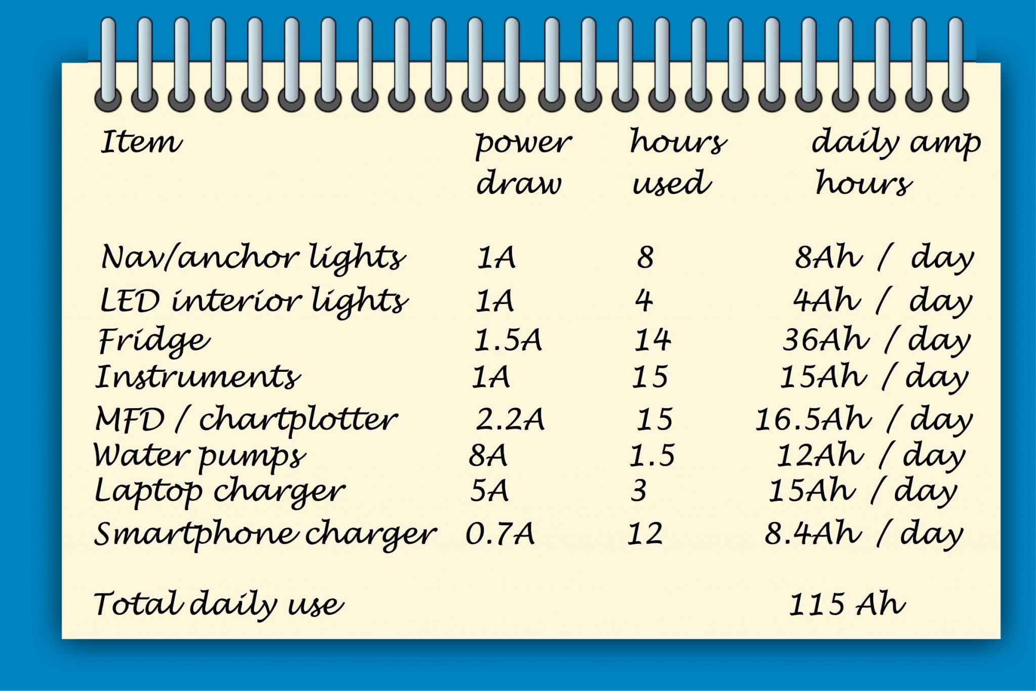
- Make a list of all your boat’s electrical equipment and the current draw of each item. You can then calculate your boat’s electrical requirements over a given period of time by adding up the total number of amp hours all of the equipment will consume (see diagram) .
Basic boat electrics
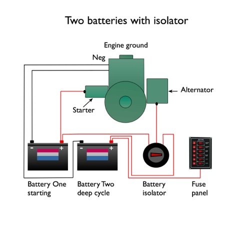
Most small boats have a 12-volt DC (direct current) system, although larger vessels will have 24-volt electrics. In most cases the system is split into two parts, one for starting the engine, the other for running all the other electrical equipment on board.
 Batteries
A boat should have two batteries (or banks of batteries) to ensure there’s always a well-charged battery for starting the engine that’s never used for anything else. In some cases there will also be a third system, with another dedicated battery (or bank of batteries) for powering high current equipment such as electric windlasses, bow thrusters and electric winches.
An automotive-type battery, of a similar specification to those used in cars, can be used to supply the starter motor with the very high loads for the few seconds it takes to start the engine. This type of battery, however, is not suitable for powering the boat’s other systems, which will typically draw a relatively small amount of power for many hours, or even days, at a stretch.
Deep-discharge (or traction) batteries are designed for slow discharge over a period of time, before being recharged when the engine is running or via shorepower chargers, or solar or wind generators. This type of use would quickly destroy an automotive battery, but a good leisure battery will withstand several hundred such cycles. However, discharging even the best deep discharge batteries below 50 per cent of their rated capacity will dramatically shorten their life.
Common problems
Most problems with marine electrical systems arise from four possible sources, a lack of maintenance, a poor standard of initial installation, insufficient battery capacity, or ineffective charging systems.
Water ingress is a frequent issue – salt water can corrode contacts very quickly. If connections are not scrupulously clean – or are loose – resistance will be increased, resulting in progressively reduced power. Contacts should be cleaned with wet and dry paper until the surface is shiny. Investigate any evidence of water ingress and eliminate the source. Also make sure you don’t confuse a battery that’s almost at the end of its life with one that is simply flat. The old battery may give reasonable voltage readings after charging, but these will fall rapidly when even a small load is drawn and the battery will soon be flat again.
Using a multimeter
If a bulb appears to be intact, a voltmeter can be used to measure the voltage at the contacts in the lamp unit. If there’s power at the switch panel, but not at the unit, you’ll need to trace the wiring and attempt to locate the break in the circuit. How easy this is to find will depend on the individual boat – some boats may have a number of joins in the wire. In any case, a boat with separate red and green pulpit lights will have a junction box somewhere near the bow, where the single supply from the distribution panel divides to take power to the two separate lamps. There will similarly be a junction somewhere for the feed to the stern light.
A meter can also be used on its resistance (Ω) setting to check whether or not a component is damaged. At the most basic level, electrical current must flow through the component in order for it to work. The resistance function of the meter passes a small current through the device being tested. If no current flows, it records infinite resistance (often shown as a figure 1 on the left hand side of a digital meter display), telling us the component doesn’t work. Note that components must be isolated from the boat’s 12V supply before testing for resistance.